the Creative Commons Attribution 4.0 License.
the Creative Commons Attribution 4.0 License.
 | 24 Apr 2020
Seismic section image detail enhancement method based on bilateral texture filtering and adaptive enhancement of texture details
Xiang-Yu Jia
The seismic section image contains a wealth of texture detail information, which is important for the interpretation of the formation profile information. In order to enhance the texture detail of the image while keeping the structural information of the image intact, a multi-scale enhancement method based on wavelet transform is proposed. Firstly, the image is wavelet decomposed to obtain a low-frequency structural component and a series of high-frequency texture detail components. Secondly, bilateral texture filtering is performed on the low-frequency structural components to filter out high-frequency noise while maintaining the edges of the image; adaptive enhancement is performed on the high-frequency detail components to filter out low-frequency noise while enhancing detail. Finally, the processed high- and low-frequency components reconstructed by wavelets can obtain a seismic section image with enhanced detail. The method of this paper enhances the texture detail information in the image while preserving the edge of the image.


A seismic section image has obvious texture characteristics; different texture areas represent different geological bodies, which play an important role in the interpretation of stratigraphic section information such as geological faults. However, in the process of generating seismic section images, the texture of seismic section image is blurred or even interrupted due to the influence of external noise on the collected seismic data, which causes interference to the interpretation of the later seismic image. Therefore, studying the texture detail enhancement method of seismic section image has both theoretical significance and potential application value.
At present, image detail enhancement methods can be divided into three categories: the first type is the airspace domain enhancement method, and representative airspace enhancement methods include global histogram equalization (Li et al., 2008; Pandey et al., 2017) and local histogram equalization (Zhu et al., 1999; Stark, 2002; Cheng and Shi, 2004; Hum et al., 2015). The former is due to the enhancement of the global image, and it does not consider the frequency and detail information of the image, which is likely to cause excessive enhancement and cannot highlight the target information in the image. The latter overcomes the defects of the foregoing method to a certain extent, but it only considers the gray distribution in the local window and does not consider the characteristics of the overall image, which tends to weaken the hierarchical sense of the image. The second type of method is a frequency domain enhancement method, including homomorphic filtering (Voicu et al., 1997; Seow and Asari, 2006) and high-pass filtering (Makandar and Halalli, 2015; Balovsyak and Odaiska, 2018). This type of method is based on an illumination-reflection model that transforms the multiplicative illumination and reflection components into an additive domain in the logarithmic domain. Then a high-pass filter in the Fourier transform domain is used; the precondition for this type of method is that the image illumination is uniform, so the enhancement effect is poor for seismic section images with high brightness and darkness areas. In addition, if the cutoff frequency of the high-pass filter is too high, it will result in severe compression of the dynamic range and loss of detail. Conversely, the dynamic range compression decreases. The third is an image enhancement method based on transform domain. In this method, the existing multiscale transform, such as wavelet transform (Tao et al., 2015; Makinana et al., 2016; Witwit et al., 2017), curvelet transform (Bhutada et al., 2011; Hashemahmed et al., 2015), and so on, is used to decompose the image. Then the coefficients of the transform are stretched, and then the enhanced image is obtained by inverse transform. This multi-scale decomposition can effectively extract the feature information of the image, such as curves and textures. However, these multi-scale decompositions cannot avoid the occurrence of round halo at the edges of the image because they use a linear filter such as a Gaussian filter in the decomposition process. At present, there is no general index to evaluate the quality of image, so the theory of image enhancement needs to be further improved. Therefore, the exploration of image enhancement technology is experimental and diverse. The image enhancement methods are often targeted so that the enhancement methods with a better effect for some kind of image may not necessarily be suitable for other images. Image enhancement processing usually uses specific methods for specific purposes (Munteanu and Rosa, 2004). Compared with conventional image, the seismic section image contains a rich texture and curve information, and there is one color. In view of these characteristics of seismic section image, we propose a wavelet decomposition method based on bilateral texture filtering and texture detail adaptive enhancement. The method firstly performs wavelet decomposition on the image, performs bilateral texture filtering on the decomposed low-frequency components, and performs adaptive detail enhancement on the high-frequency components. The processed high- and low-frequency components are wavelet reconstructed to obtain a seismic section image with enhanced texture details. The biggest feature of this method is the ability to separate the texture details in the image while maintaining the edge information of the original image during processing. This property is very beneficial to the enhancement of image texture details.
In Sect. 1 of this paper, the background and significance of the research are discussed. The deficiencies of the existing algorithms are analyzed for the characteristics of seismic profiles. The idea of image texture detail enhancement based on wavelet transform is proposed. Section 2 presents the seismic detail image texture detail enhancement model and algorithm flow. Section 3 details the image enhancement contrast experiment.
The wavelet transform can effectively separate the characteristics of low-frequency and high-frequency components of the image, and the seismic section image is decomposed into a low-frequency structural image and multiple high-frequency texture images by wavelet transform. On the low-frequency structural image, the bilateral texture filtering method is used to quickly and accurately estimate and remove the high-frequency noise of the image. On the high-frequency texture image, multi-scale detail enhancement and denoising are performed on the detail component reflecting the texture content of the image. Then, an adaptive optimization strategy is used to improve the contrast of the image after the above processing to obtain the final enhanced image. The processing flow is shown in Fig. 1.
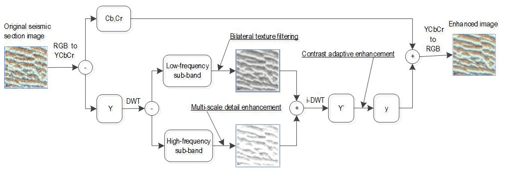
The image texture detail enhancement method shown in Fig. 1 is as follows:
-
Step 1 entails converting the seismic section image from the RGB space to the YCbCr space and decomposition to obtain the luminance component Y and the chrominance components Cb and Cr.
-
Step 2 entails performing single-layer discrete wavelet decomposition on the luminance component Y to obtain a low-frequency structural image and three high-frequency texture images.
-
Step 3 entails performing bilateral texture filtering on the low-frequency sub-band after wavelet transform to filter out texture details in the image and keep the image edges unambiguous.
-
Step 4 entails performing multi-scale adaptive enhancement on each high-frequency sub-band after wavelet transform to enhance texture detail information in the seismic image.
-
Step 5 entails performing inverse wavelet transform on the high- and low-frequency sub-bands processed in steps 3 and 4 to synthesize a new luminance component Y′.
-
Step 6 entails performing contrast adaptive enhancement on Y′ to obtain the new luminance component y.
-
Step 7 entails combining the luminance component y with the chrominance components Cb and Cr and converting it into the RGB space, that is, obtaining a seismic section image with enhanced texture details.
The following is an introduction to the implementation of important modules in the algorithm.
2.1 Wavelet decomposition of luminance component Y
The two-dimensional discrete wavelet transform includes two processes of decomposition and reconstruction, wherein the two-dimensional wavelet decomposition process is as follows: first, a one-dimensional wavelet transform is performed on the row data of the image to obtain the low-frequency component L and the high-frequency component H in the horizontal direction. Then, one-dimensional wavelet transform is performed on each column on the low- and high-frequency components after the transformation, and four components LL, LH, HL, and HH are obtained in the horizontal and vertical directions, respectively. The reconstruction process of two-dimensional wavelet is as follows: first, one-dimensional inverse wavelet transform is performed on the image column data in the vertical direction, and then one-dimensional inverse wavelet transform is performed on the image row data in the horizontal direction, and finally the reconstructed image is obtained. The decomposition and reconstruction process are shown in Fig. 2.
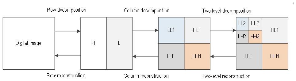
Considering the real-time performance of the calculation, the Haar wavelet is used to perform single-layer wavelet decomposition on the luminance component Y to obtain a low-frequency structural image and three high-frequency texture images. It can be seen from Fig. 2 that the obtained low-frequency sub-band has an area of only 1∕4 of the original image, so the bilateral texture filtering on the low-frequency sub-band greatly improves the processing speed.
2.2 Bilateral texture filtering of wavelet low-frequency sub-band
Before introducing bilateral texture filtering, review the bilateral filtering with groundbreaking work (Tomasi and Manduchi, 1998). Given an input image I, a reference image G, and the output of the bilateral filtering is J, the following relationship exists:
where kp is the normalization factor, Jp is the weighted mean of all Iq of pixel p in neighborhood Ωp, and f and g are two typical Gaussian functions.
The selection of the reference image G has a great influence on the bilateral filtering effect, and the bilateral texture filtering is realized by cleverly selecting the reference image G. Bilateral texture filtering can better filter out texture details in images while keeping edges unambiguous (Cho et al., 2014). The core idea is to obtain the texture features by the method of partial block transfer, which can effectively realize the soft segmentation of the image texture region and preserve the structure of the image.
Setting the size of image block as k×k, for each pixel p in image I, there are k2 image blocks containing p. We denote the image block centered on q as Ωq. In these blocks, Ωq is assumed to be a block containing the least significant structure edges. Once Ωq is found to satisfy this property, we perform average filtering within this block to get the pixel value of the current point, denoted as Bq, and use this result as a bilateral filtered reference image. Given the input image I, first apply the mean filter kernel of k×k to calculate the mean of the image I, denoted as B. For each pixel p, calculate its tonal range according to Eq. (2):
where Imax(Ωq) and Imin(Ωq) represent the maximum and minimum values of the pixel values in the block, respectively; in the neighborhood of this pixel, the block with the smallest Δ(Ωq) is found, and the reference image Gp in Eq. (1) is replaced with Bq.
Since the definition of the tonality range of Eq. (2) is relatively simple, the concept of related total variation is introduced to improve (Xu et al., 2012), and the correlation total variation is defined as
where |(∂I)r| denotes the gradient energy of r∈Ωq and ε is a small normal number, preventing the denominator from being zero.
From Eq. (3), the mRTV value will be very small in the smooth region of the image and also very sensitive to noise. To solve this problem, when assigning the Bq value to the reference image Gp, it is necessary to check the mRTV values of Ωp and Ωq, and if and only if mRTV(Ωq)<mRTV(Ωp), assign the Bq value to the reference image Gp, when the two mRTV values are close, assigning Bp value to the reference image Gp. To achieve this idea, the final reference image G′ is obtained by linear interpolation between images B and G:
where
In the formula, the weight is small in the smooth and textured regions but larger in the vicinity of the boundary; σα controls the degree of change from the edge to the smooth/texture transition, generally taking σα=5k.
The bilateral texture filtering steps are summarized as follows:
-
Step 1 consists in inputting image I and averaging filtering image I to obtain B.
-
Step 2 consists in the calculation of the mRTV value of each pixel p in the image I according to Eq. (3).
-
Step 3 consists in, for each pixel p, finding the pixel q with the smallest mRTV value in Ωp, where we let Gp=Bq.
-
Step 4 consists in calculating the reference image G′ using Eq. (4).
-
Step 5 consists in using G′ as the reference image and I as the input image into Eq. (1). Thereby, the bilateral texture filtering of image I can be realized, and the filtered image J is output.
2.3 Detail enhancement of wavelet high-frequency sub-band
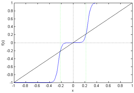
In order to enhance the useful information of the texture while suppressing the noise information, the wavelet high-frequency sub-band is detail enhanced. That is, the following adaptive enhancement transform is used for each high-frequency sub-band obtained by wavelet transform (Zhang et al., 2005). The specific transformation formula is as follows:
where
b and c are used to control the magnitude of the enhancement. As can be seen from Fig. 3, the function f(x) mainly enhances the middle portion of the image gray value, the smaller coefficient corresponds to noise, and the larger coefficient corresponds to the texture detail of the image.
After processing the low-frequency sub-band and the high-frequency sub-band according to the method given in Sect. 2.2 and 2.3, the inverse wavelet transform can be used to obtain the luminance component Y after the texture detail is enhanced. By synthesizing the luminance component Y and the chrominance components Cb and Cr into an RGB format, a seismic section image with enhanced texture details can be obtained.
In order to verify the effectiveness of the proposed algorithm, we selected two representative enhancement algorithms: wavelet enhancement (Sakellaropoulos et al., 2003) and bilateral filtering enhancement (Farbman et al., 2008).
3.1 Experiment 1
Figure 4a is a seismic section image. Due to seismic data noise and noise introduced during seismic data processing, the image texture information is not clear, which affects subsequent image interpretation. According to our algorithm idea, the experimental steps and results are as follows:
-
In Step 1, Fig. 4a is converted from the RGB format to the YCbCr format, and the luminance component Y and the chrominance components Cb and Cr are obtained as shown in Fig. 4b–d.
-
In Step 2, single-layer Haar wavelet decomposition is performed on the luminance component Y to obtain a low-frequency structural component cA and three high-frequency detail components cH, cV, and cD, as shown in Fig. 5.
-
In Step 3, the component cA shown in Fig. 5a is filtered by bilateral texture filtering, in which the block size k=3, and the result after filtering is shown in Fig. 5e. The same method is applied to the components cH, cV, and cD shown in Fig. 5b–d, and the results after filtering are shown in Fig. 5f–h.
-
In Step 4, wavelet reconstruction is performed on the component shown in Fig. 6 to form the brightness component Y, and then it is converted into RGB format after combining with the chromaticity component CbCr, thereby obtaining a seismic section image with enhanced texture details, as shown in Fig. 6d. The enhanced results using wavelet transform and bilateral filtering are shown in Fig. 6b and c.
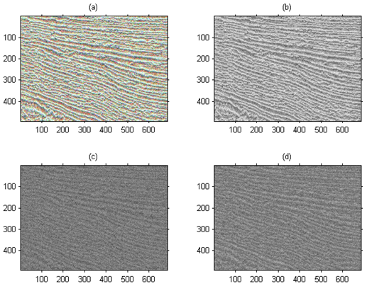
Figure 4Converting a seismic section image from RGB format to YcbCr format. (a) Original seismic image. (b) The brightness component Y of the image (a) after the format conversion. (c, d) Chroma component Cb and Cr of image (a) after format conversion.
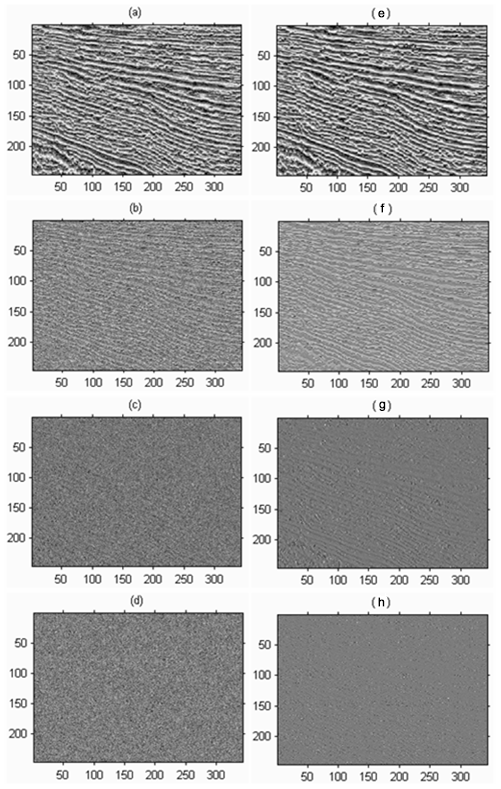
Figure 5(a) Low-frequency structure image component cA. (b) Lateral high-frequency detail component cH. (c) Longitudinal high-frequency detail component cV. (d) Diagonal high-frequency detail component cD. (e) The results obtained by bilateral texture filtering of (a). (f) Obtaining the results after detail enhancement of (b). (g) Obtaining the results after detail enhancement of (c). (h) The results are enhanced by the detail enhancement of (d).
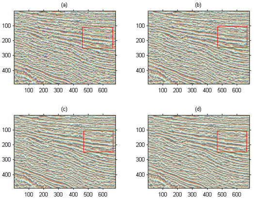
Figure 6Comparison of algorithm results. The red box shows the contrast enhancement of local texture feature of seismic section image. (a) Original seismic section image. (b) Wavelet enhancement algorithm. (c) Bilateral filtering enhancement algorithm. (d) Our algorithm.
As can be seen from Fig. 6, the wavelet transform enhancement method is mainly for the enhancement of point singular features, and there is often no good processing result for the lines in the image. Therefore, the large-area oscillation period texture in the seismic section image cannot be well processed, and a false edge is generated during the processing. Although the bilateral filtering enhancement method can enhance the image edge information well, the enhancement effect of the texture part is still unsatisfactory. The method we proposed gives full play to the advantages of bilateral texture filtering in image texture processing, which can better enhance the unclear texture details in the original image, and at the same time enhance the texture information without destroying the image edge information, thus obtaining the rich texture details of the seismic section image. It not only enhances the visualization effect but also provides more abundant and accurate information for the geologist's next seismic section image interpretation. The red box in Fig. 6d shows that the seismic profile image has clear image texture features. Compared with Fig. 6a–c, it reduces data noise interference and makes it easier to extract stratigraphic sequence features.
3.2 Experiment 2
Figure 7 shows the comparison results of the second set of experimental image enhancements, where Fig. 7a is the original image. From the visual point of view, the method of this paper better enhances the unclear details in the original image and obtains rich texture features. Figure 7b is a wavelet enhancement result. To some extent, this method enhances the unclear texture details in the original image, but the enhancement effect of the original image is not obvious for the areas with rich linear texture information. Figure 7c shows the effect of bilateral filtering enhancement. This method has a large advantage in smaller wave enhancement, but the overall detail enhancement effect is far from Fig. 7d. Our method not only improves the contrast of the image but also has a good enhancement effect on the edge of the seismic section image and texture details.
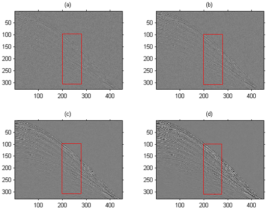
Figure 7The results of our algorithm and comparison algorithm (The red box shows rock type characteristics of the depositional sequence in the seismic event). (a) Original seismic section images; (b) wavelet enhancement algorithm; (c) bilateral filtering enhancement algorithm; (d) our algorithm.
In the actual seismic section data acquisition, limited by the complex environment or acquisition instrument, the acquired data inevitably contain a lot of noise, which affects the signal-to-noise ratio and visibility of the seismic section image, and then may affect the subsequent data processing and stratigraphic data interpretation work. As shown in Fig. 7a, the events of the seismic section are dense, and part of it is curved; because the figure contains a large amount of noise, the data noise makes the details of seismic wave front very fuzzy. After using the algorithm in this paper, the features of event become clear, and the details of seismic wave front and edge are also highlighted, which is convenient for geologists to interpret the formation profile information. The red box in Fig. 7 shows rock type characteristics of the depositional sequence in the seismic event. From Fig. 7d, it can be seen that the reconstructed seismic events are smooth and continuous, and the high-amplitude event recovery is obvious.
3.3 Experiment 3
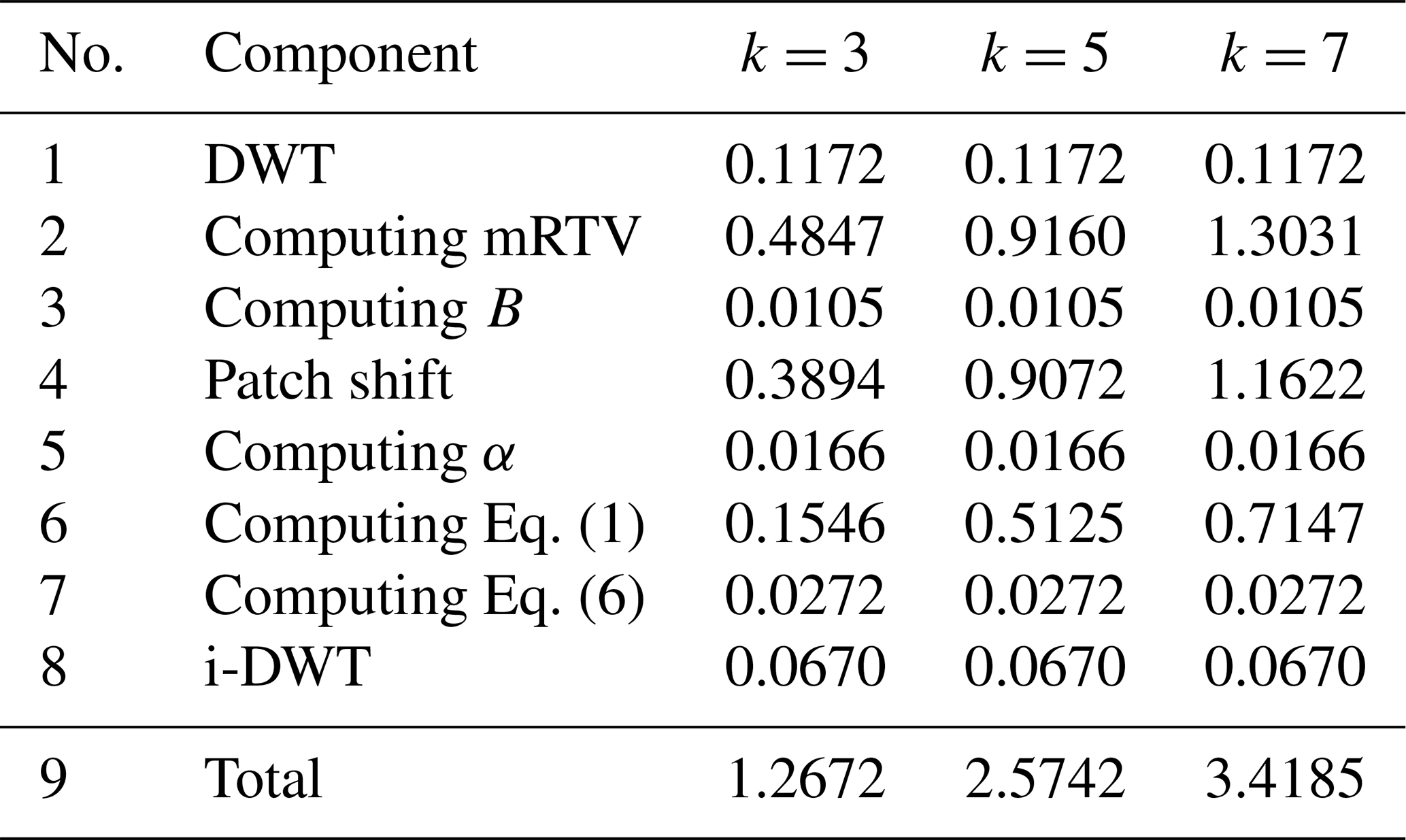
This experiment mainly tests the processing time of the algorithm in this paper. The CPU of the test computer was Intel® Core™ i5-4590 3.30 GHz, the RAM size was 4 G, and the software platform was MATLAB. Because the proposed algorithm combines wavelet decomposition with bilateral filtering, the image enhancement effect is better than wavelet enhancement algorithm and bilateral filtering algorithm, but the running time of this algorithm is slower than wavelet enhancement algorithm and bilateral filtering enhancement algorithm on this platform. Table 1 shows the time-consuming statistics of the various components of the algorithm in the test platform. The picture used in the test is a grayscale image of 800×600; k is patch size.
Table 1Time consumption of each component of the algorithm in this paper (s).
We proposed a texture detail enhancement method for seismic section image. Wavelet transform can effectively separate structure information (low-frequency sub-band) and detail information (high-frequency sub-band) of an image. High-frequency noise in structural information can be estimated and removed effectively by using bilateral texture filter in the low-frequency sub-band. In the high-frequency sub-band, adaptive enhancement transform can be used to enhance the image edge and texture information, effectively removing the low-frequency noise. Experimental results show that the algorithm cannot only effectively enhance the edge and texture information of the image but also reduce the impact of noise.
Data and results of calculations are available by email request to Xiang-Yu Jia (email: jiaxy1999@163.com).
XYJ designed the study, performed the research, analyzed data, and wrote the paper. CLDY contributed to refining the ideas, carrying out additional analyses, and finalizing this paper.
The authors declare that they have no conflict of interest.
This research has been supported by the Natural Science Foundation of Shandong Province (grant no. ZR2018MEE008) and the Key Research and Development Program of Shandong Province, China (grant no. 2017GSF20115).
This paper was edited by Luciano Telesca and reviewed by Sergio Chávez-Pérez and one anonymous referee.
Balovsyak, S. V. and Odaiska, K. S.: Automatic determination of the gaussian noise level on digital images by high-pass filtering for regions of interest, Cybern. Syst. Anal., 54, 662–670, https://doi.org/10.1007/s10559-018-0067-3, 2018.
Bhutada, G. G., Anand, R. S., and Saxena, S. C.: Edge preserved image enhancement using adaptive fusion of images denoised by wavelet and curvelet transform, Digit. Signal Process., 21, 118–130, https://doi.org/10.1016/j.dsp.2010.09.002, 2011.
Cheng, H. D. and Shi, X. J.: A simple and effective histogram equalization approach to image enhancement, Digit. Signal Process., 14, 158–170, https://doi.org/10.1016/j.dsp.2003.07.002, 2004.
Cho, H., Lee, H., Kang, H., and Lee, S.: Bilateral texture filtering, ACM T. Graphic., 33, 1–8, https://doi.org/10.1145/2601097.2601188, 2014.
Farbman, Z., Fattal, R., Lischinski, D., and Szeliski, R.: Edge-preserving decompositions for multi-scale tone and detail manipulation, ACM T. Graphic., 27, 1–10, https://doi.org/10.1145/1360612.1360666, 2008.
Hashemahmed, H., Kelash, M. H., Tolba, M., and Bayoumy, M.: Fingerprint image enhancement based on threshold fast discrete curvelet transform (FDCT) and gabor filters, International Journal of Computer Applications (IJCA), 110, 33–41, https://doi.org/10.5120/19299-0746, 2015.
Hum, Y. C., Lai, K. W., and Mohamad Salim, M. I.: Multiobjectives bihistogram equalization for image contrast enhancement, Complexity, 20, 22–36, https://doi.org/10.1002/cplx.21499, 2015.
Li, G., Luo, W., Pei, L., and Lv, H.: Fusion Enhancement of Color Image Based on Global Histogram Equalization, in: International Conference on Computer Science and Software Engineering, Hubei, China, 12–14 December 2008, 205–208, 2008.
Makandar, A. and Halalli, B.: Image enhancement techniques using highpass and lowpass filters, International Journal of Computer Applications (IJCA), 109, 21–27, https://doi.org/10.5120/19256-0999, 2015.
Makinana, S., Khanyile, P. N., and Khutlang, R.: Latent fingerprint wavelet transform image enhancement technique for optical coherence tomography, in: International Conference on Artificial Intelligence and Pattern Recognition, Lodz, Poland, 19–21 September, IEEE, 7–11, 2016.
Munteanu, C. and Rosa, A., Gray-scale image enhancement as an automatic process driven by evolution, IEEE T. Syst. Man Cy. B, 34, 1292–1298, https://doi.org/10.1109/TSMCB.2003.818533, 2004.
Pandey, A. K., Sharma, P. D., Dheer, P., Parida, G. K., Goyal, H., and Patel, C.: Investigating the role of global histogram equalization technique for 99mTechnetium-Methylene diphosphonate bone scan image enhancement, Indian Journal of Nuclear Medicine, 32, 283–288, https://doi.org/10.4103/ijnm.IJNM_61_17, 2017.
Sakellaropoulos, P., Costaridou, L., and Panayiotakis, G.: A wavelet-based spatially adaptive method for mammographic contrast enhancement, Phys. Med. Biol., 48, 787, https://doi.org/10.1088/0031-9155/48/6/307, 2003.
Seow, M. J. and Asari, V. K.: Ratio rule and homomorphic filter for enhancement of digital color image, Neurocomputing, 69, 954–958, https://doi.org/10.1016/j.neucom.2005.07.003, 2006.
Stark, J. A.: Adaptive image contrast enhancement using generalizations of histogram equalization, IEEE T. Image Process., 9, 889–896, https://doi.org/10.1109/83.841534, 2002.
Tao, L., Wei, Z., and Yan, S.: A novel image enhancement algorithm based on stationary wavelet transform for infrared thermography to the de-bonding defect in solid rocket motors, Mech. Syst. Signal Pr., 62–63, 366–380, https://doi.org/10.1016/j.ymssp.2015.03.010, 2015.
Tomasi, C. and Manduchi, R.: Bilateral filtering for gray and color images, in: Sixth International Conference on Computer Vision, Bombay, India, 7 January 1998, IEEE, 839–846, 1998.
Voicu, L. I., Myler, H. R., and Weeks, A. R.: Practical considerations on color image enhancement using homomorphic filtering, J. Electron. Imaging, 6, 108–113, https://doi.org/10.1117/12.251157, 1997.
Witwit, W., Zhao, Y., Jenkins, K., and Zhao, Y.: Satellite image resolution enhancement using discrete wavelet transform and new edge-directed interpolation, J. Electron. Imaging, 26, 023014, https://doi.org/10.1117/1.JEI.26.2.023014, 2017.
Xu, L., Yan, Q., Xia, Y., and Jia, J.: Structure extraction from texture via relative total variation, ACM T. Graphic., 31, 1391–13910, https://doi.org/10.1145/2366145.2366158, 2012.
Zhang, Z., Ma, S., and Han, X.: Multiscale feature extraction of finger-vein patterns based on curvelets and local interconnection structure neural network, in: International Conference on Neural Networks and Brain, Beijing, China, 13–15 October, 2005, 1081–1084, 2005.
Zhu, H., Chan, F. H. Y., and Lam, F. K.: Image contrast enhancement by constrained local histogram equalization, Comput. Vis. Image Und., 73, 281–290, https://doi.org/10.1006/cviu.1998.0723, 1999.